|
|
本帖最后由 lon8699 于 2016-10-22 18:02 编辑
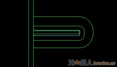
要改扁铁水密补板
 -->
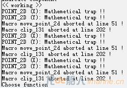
,由于之前不是本人编制,自己重新编写补板语句发现一直报错
 -->
,分析错误所在语句,但无法发现问题所在,请哪位高人帮忙分析解决一下,谢谢。附件为补板语句以及加载生成LST文件
! Main procedure of clip_1
! **************************************************************
! Assign treatment code.
ASSIGN, POS_CODE, 1;
! FIXED_R1 is the corner radius (15 mm).
ASSIGN, FIXED_R1, 3.0;
ASSIGN, FIXED_R3, 75.0;
IF, CLIP_LOC == 1;
!! DIST1 is the gap between the bottom side of the clip and the plate carrying the profile.
!! DIST2 is the width of the clip. It depends on the clip side, so it will be calculated later.
!! DIST3 is the gap between the top side of the clip and the (top side) of the flange.
ASSIGN, DIST1, 0;
ASSIGN, DIST3, 75.0;
ASSIGN, OVERLAP, 50.0;
GET/STRUCTURE = ( V2_X, V2, 'VEC', 'X');
GET/STRUCTURE = ( V2_Y, V2, 'VEC', 'Y');
GET/STRUCTURE = ( V3_X, V3, 'VEC', 'X');
GET/STRUCTURE = ( V3_Y, V3, 'VEC', 'Y');
!! V1 is a vector along the web of the profile cross section,
! i.e. along the V-axis of the local clip coordinate system.
VECTOR_2D, V1, 0.0, 1.0;
! Vector in the negative direction of V1.
VECTOR_2D, V1_NEG, 0.0, -1.0;
! Vector in the negative direction of V2.
VECTOR_2D, V2_NEG, -V2_X, -V2_Y;
VECTOR_2D, V3_NEG, -V3_X, -V3_Y;
! ---------------------------------------------------------------
! Define clip contour node points on non-mould line side
! ---------------------------------------------------------------
! Set DIST2
ASSIGN, DIST2, 25 + OVERLAP;
POINT_2D, QO, X0, Y0;
POINT_2D, CO, X0+PROF_PARAM3+ 13, Y0 + DIST1;
ASSIGN, DIST_TEMP1, 75.0;
POINT_2D, C1, X0+PROF_PARAM3+DIST_TEMP1, Y0 + DIST1;
ASSIGN, DIST_TEMP2, PROF_PARAM1+GAP_T+OVERLAP;
! CALL, 'move_point_2d',Q0,V1,DIST_TEMP2,Q1;
POINT_2D, Q1, X0, Y0+DIST_TEMP2;
CALL, 'fillet_radius_2d', C1, V1, Q1, V3_NEG, FIXED_R3, C2, C3, RES;
POINT_2D, C6, X0-75, Y0 + DIST1;
CALL, 'intersect_line_2d',Q0,V3_NEG,C6,V1,C6,RES;
POINT_2D, C7, X0-13, Y0+DIST1;
CALL, 'intersect_line_2d',Q0,V3_NEG,C7,V1,C7,RES;
POINT_2D, C8, X0-3, Y0+DIST1+10;
POINT_2D, C13, X0+PROF_PARAM3+3, Y0+DIST1+10;
CALL, 'fillet_radius_2d', Q1, V3_NEG, C6, V1_NEG, FIXED_R3, C4, C5, RES;
ASSIGN, DIST_TEMP3, PROF_PARAM2 + 3;
CALL, 'move_point_2d', Q0, V1, DIST_TEMP3, Q2;
CALL, 'fillet_radius_2d', C8, V1, Q2, V3, FIXED_R1, C9, C10, RES;
CALL, 'fillet_radius_2d', Q1, V3, C13, V1_NEG, FIXED_R1, C11, C12, RES;
!!!---------------------------------------------------------------
!!!---------------------------------------------------------------
CONTOUR, CLIP_CONTOUR, C0
/LINEEND = C1
/LINEEND = C2
/ARCRADIUS = ( C3, FIXED_R3)
/LINEEND = C4;
/ARCRADIUS = ( C5, FIXED_R3)
/LINEEND = C6
/LINEEND = C7
/LINEEND = C8
/LINEEND = C9
/ARCRADIUS = ( C10, -FIXED_R1)
/LINEEND = C11
/ARCRADIUS = ( C12, -FIXED_R1)
/LINEEND = C13
/LINEEND = C0;
|
|