12
返回列表 发新帖
楼主: DraftMan
收起左侧

[轮机] 中航鼎衡:直接驱动永磁轴发电机驱动,什么概念?优势何在?

[复制链接]
发表于 2017-2-18 11:15 | 显示全部楼层 来自: 中国吉林四平
fattom

打个岔,爱迪生好像没发明电灯泡,弧光灯之前就有,他只是通过N次试验找到了竹丝,进而钨丝,是电灯泡的寿命大大延长了。  发表于 2017-2-18 09:59

哈哈,这个吗你说的倒是有点道理。是从哪个少儿科普读物里看到的?能不能推荐给我看看。

“电灯泡”是比较通俗的说法,就是指你说的开始用的是碳化竹丝,后来又改进成钨丝的那种适合广泛生活照明的放在抽过真空的玻璃泡,靠电阻发热而发光那种照明工具。弧光灯根本就是另一类东东,发光原理都不一样,不过也放在一个抽过真空的玻璃泡里。

哈哈,我咋觉得这样说话很累呀!
回复 支持 反对

使用道具 举报

龙船学院
发表于 2017-2-18 11:51 | 显示全部楼层 来自: 中国上海
黑哥250 发表于 2017-2-14 18:14
这种东东已经出现有一段时间啦。

你用常理想想,如果光有优点没有缺点的话,短期内岂不是大部分新船都会 ...

"举个极端的例子,如果装卸货时船本身需要大功率电力的船就不能用。"

能详细说明一下,“啥”不能用?
轴带发电机能在船舶装卸货阶段使用?
回复 支持 反对

使用道具 举报

发表于 2017-2-18 11:54 | 显示全部楼层 来自: 中国上海
你发个帖子,结果楼下的都跑题了,还... 出来评理。。。
回复 支持 反对

使用道具 举报

发表于 2017-2-18 11:57 | 显示全部楼层 来自: 中国上海
黑哥250 发表于 2017-2-17 12:26
我是在说那条化学品船的船东选了这套系统,我对他的思维方式不理解。

你是不是误解啦?以为我在说你。 ...

“我是在说那条化学品船的船东选了这套系统,我对他的思维方式不理解。”
为啥不理解?

PMG, 可以PTO+PTI(POWER BOOSTER)

回复 支持 反对

使用道具 举报

发表于 2017-2-18 12:01 | 显示全部楼层 来自: 中国上海
frankcheng 发表于 2017-2-17 13:18
这个帖子的主题是: AFE 直接驱动轴发.
中航鼎衡的这条船,是双燃料低速主机, 不存在fix RPM工况, 所以如 ...

“但是, 如果是单一LNG燃料推进系统, 要么配双LNG罐( 或者单罐+2个TCS), 要么加柴油发电机驱动的PTI. 这条船的船东是北欧的, 未来肯定要建造单一LNG为燃料的船舶. 即使不考虑低速机驱动轴发带来的经济性, 船东在这条双燃料船舶上加PTI作为技术储备及技术验证, 也非常符合逻辑.“

是否要编辑 一下,表达准确一些?

回复 支持 反对

使用道具 举报

发表于 2017-2-18 13:07 | 显示全部楼层 来自: 中国上海
黑哥250 发表于 2017-2-18 11:15
fattom

打个岔,爱迪生好像没发明电灯泡,弧光灯之前就有,他只是通过N次试验找到了竹丝,进而钨丝,是 ...

"别胡说啦,欧洲大概有二十几个船舶轮机设计的头儿都是我的同学,那些人的思维不会这样乱的!"
推荐几位? 如何?
回复 支持 反对

使用道具 举报

发表于 2017-2-18 13:22 | 显示全部楼层 来自: 中国上海
江海直达 发表于 2017-2-18 11:54
你发个帖子,结果楼下的都跑题了,还... 出来评理。。。

A permanent magnet synchronous generator is a generator where the excitation field is provided by a permanent magnet instead of a coil. The term synchronous refers here to the fact that the rotor and magnetic field rotate with the same speed, because the magnetic field is generated through a shaft mounted permanent magnet mechanism and current is induced into the stationary armature
Synchronous generators are the majority source of commercial electrical energy. They are commonly used to convert the mechanical power output of steam turbines, gas turbines, reciprocating engines and hydro turbines into electrical power for the grid. Some designs of Wind turbines also use this generator type.


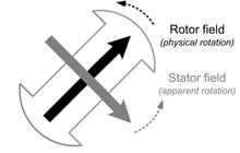
In the majority of designs the rotating assembly in the center of the generator—the "rotor"—contains the magnet, and the "stator" is the stationary armature that is electrically connected to a load. As shown in the diagram above, the perpendicular component of the stator field affects the torque while the parallel component affects the voltage. The load supplied by the generator determines the voltage. If the load is inductive, then the angle between the rotar and stator fields will be greater than 90 degrees which corresponds to an increased generator voltage. This is known as an overexcited generator. The opposite is true for a generator supplying a capacitive load which is known as an underexcited generator. A set of three conductors make up the armature winding in standard utility equipment, constituting three phases of a power circuit—that correspond to the three wires we are accustomed to see on transmission lines. The phases are wound such that they are 120 degrees apart spatially on the stator, providing for a uniform force or torque on the generator rotor. The uniformity of the torque arises because the magnetic fields resulting from the induced currents in the three conductors of the armature winding combine spatially in such a way as to resemble the magnetic field of a single, rotating magnet. This stator magnetic field or "stator field" appears as a steady rotating field and spins at the same frequency as the rotor when the rotor contains a single dipole magnetic field. The two fields move in "synchronicity" and maintain a fixed position relative to each other as they spin.[1]
They are known as synchronous generators because f, the frequency of the induced voltage in the stator (armature conductors) conventionally measured in hertz, is directly proportional to RPM, the rotation rate of the rotor usually given in revolutions per minute (or angular speed). If the rotor windings are arranged in such a way as to produce the effect of more than two magnetic poles, then each physical revolution of the rotor results in more magnetic poles moving past the armature windings. Each passing of a north and south pole corresponds to a complete "cycle" of a magnet field oscillation. Therefore, the constant of proportionality is P             120                                     {\displaystyle {\frac {\text{P}}{120}}}    , where P is the number of magnetic rotor poles (almost always an even number), and the factor of 120 comes from 60 seconds per minute and two poles in a single magnet; f         (           Hz                      )                  =         R         P         M         P             120                                     {\displaystyle f\left({\text{Hz}}\right)=RPM{\frac {\text{P}}{120}}}    .[2]
The power in the prime mover is a function of RPM and torque. P           m                             =         T           m                             ∗         R         P         M                 {\displaystyle P_{m}=T_{m}*RPM}    where P           m                                     {\displaystyle P_{m}}    is mechanical power in Watts, T           m                                     {\displaystyle T_{m}}    is the torque with units of N               ∗               m                          r               a               d                                                  {\displaystyle {\frac {N*m}{rad}}}    , and RPM is the rotations per minute which is multiplied by a factor of 2         π                 {\displaystyle 2\pi }    to give units of R               a               d               i               a               n               s                          S               e               c                                                  {\displaystyle {\frac {Radians}{Sec}}}    . By increasing the torque on the prime mover, a larger electrical power output can be generated.


In practice, the typical load is inductive in nature. The diagram above depicts such an arrangement. E           i                                     {\displaystyle E_{i}}    is the voltage of the generator, and V           a                                     {\displaystyle V_{a}}    and I           a                                     {\displaystyle I_{a}}    are the voltage and the current in the load respectively and θ                 {\displaystyle \theta }    is the angle between them. Here, we can see that the resistance, R, and the reactance, X           d                                     {\displaystyle X_{d}}    , play a role in determining the angle δ                 {\displaystyle \delta }    . This information can be used to determine the real and reactive power output from the generator.


In this diagram, V           t                                     {\displaystyle V_{t}}    is the terminal voltage. If we ignore the resistance as shown above, we find that the power can be calculated:[3]
I           a                             =         |                              E                 i                                               |                              ∠               δ               −               |                              V                 t                                               |                                         j               X                 d                                                                                  {\displaystyle I_{a}={\frac {|E_{i}|\angle \delta -|V_{t}|}{jX_{d}}}}   


S         =         P         +         j         Q         =         V           t                             I           ⋆                             =         |                              V                 t                                               |                              |                              E                 i                                               |                              ∠               (               −               δ               )               −               |                              V                 t                                               |                                  2                                                          −               j               X                 d                                                                          =         |                              V                 t                                               |                              |                              E                 i                                               |                              (               c               o               s               (               δ               )               −               j               s               i               n               (               δ               )               )               −               |                              V                 t                                               |                                  2                                                          −               j               X                 d                                                                                  {\displaystyle S=P+jQ=V_{t}I^{\star }={\frac {|V_{t}||E_{i}|\angle (-\delta )-|V_{t}|^{2}}{-jX_{d}}}={\frac {|V_{t}||E_{i}|(cos(\delta )-jsin(\delta ))-|V_{t}|^{2}}{-jX_{d}}}}   


Breaking the apparent power into Real and Reactive power, we get:
P         =         |                              V                 t                                               |                              |                              E                 i                                               |                                         X               d                                                         s         i         n         (         δ         )                 {\displaystyle P={\frac {|V_{t}||E_{i}|}{X_{d}}}sin(\delta )}   

, Q         =         |                              V                 t                                               |                                         X               d                                                         (         |                  E           i                             |                  c         o         s         (         δ         )         −         |                  V           t                             |                  )                 {\displaystyle Q={\frac {|V_{t}|}{X_{d}}}(|E_{i}|cos(\delta )-|V_{t}|)}   


In a permanent magnet generator, the magnetic field of the rotor is produced by permanent magnets. Other types of generator use electromagnets to produce a magnetic field in a rotor winding. The direct current in the rotor field winding is fed through a slip-ring assembly or provided by a brushless exciter on the same shaft.
Permanent magnet generators (PMG's) or alternators (PMA's) do not require a DC supply for the excitation circuit, nor do they have slip rings and contact brushes. The future economics of PMA's or PMG's as they are sometimes called is now largely co***olled by China as they have the global monopoly on neodymium material used to make the most powerful and also the most desirable types of magnets used today. The flux density of high performance permanent magnets is limited giving China an unfair advantage in setting the global price. A key disadvantage in PMA's or PMG's is that the air gap flux is not co***ollable, so the voltage of the machine cannot be easily regulated. A persistent magnetic field imposes safety issues during assembly, field service or repair. High performance permanent magnets, themselves, have structural and thermal issues. Torque current MMF vectorially combines with the persistent flux of permanent magnets, which leads to higher air-gap flux density and eventually, core saturation. In this permanent magnet alternators the speed is directly proportional to the output voltage of the alternator.
回复 支持 反对

使用道具 举报

发表于 2017-2-18 13:35 | 显示全部楼层 来自: 中国吉林四平
江海直达 发表于 2017-2-18 13:07
"别胡说啦,欧洲大概有二十几个船舶轮机设计的头儿都是我的同学,那些人的思维不会这样乱的!"
推荐几位 ...

推荐给你?你配吗?
回复 支持 反对

使用道具 举报

发表于 2017-2-18 13:53 | 显示全部楼层 来自: 中国上海
江海直达 发表于 2017-2-18 13:22
A permanent magnet synchronous generator is a generator where the excitation field is provided by  ...

https://www.youtube.com/watch?v=-EzUchkAuAY
回复 支持 反对

使用道具 举报

发表于 2017-2-18 13:56 | 显示全部楼层 来自: 中国上海
江海直达 发表于 2017-2-18 13:53
https://www.youtube.com/watch?v=-EzUchkAuAY

Advantages and Disadvantages of the PMSG Generator
                                                        Posted on September, 10                                                                 in Power Electronics for Renewable and Distributed Energy Systems                                                         
The PMSG generator offers many advantages. The PMSG machine is the most efficient of all electric machines since it has a movable magnetic source inside itself. Use of permanent magnets for the excitation consumes no extra electrical power. Therefore, copper loss of the exciter does not exist and the absence of mechanical commutator and brushes or slip rings means low mechanical friction losses. Another advantage is its compactness.
The recent i***oduction of high-energy density magnets (rare-earth magnets) has allowed the achievement of extremely high flux densities in the PMSG gen erator, therefore rotor winding is not required. These in turn allow the generator to be of small, light, and rugged structure. As there is no current circulation in the rotor to create a magnetic field, the rotor of a PMSG generator does not heat up. The only heat production is on the stator, which is easier to cool down than the rotor because it is on the periphery of the generator and the static.
The absence of brushes, mechanical commutators, and slip rings suppresses the need for the associated regular maintenance and suppresses the risk of failure in these elements. They have very long lasting winding insulation, bearing, and magnet life length. Since no noise is associated with the mechanical contacts and the driving converter switching frequency could be above 20 kHz producing only ultrasound inaudible for human beings.
When the PMSG generator is compared with respect to the conventional ones for low-speed water flows, the list of advantages is increased: (1) No speed multiplier or gears since there may be multiple permanent or electromagnets in the rotor for more current production; (2) Few maintenance services because of its simplified mechanical design; (3) Easy mechanical interface; (4) Cost optimiza tion; (5) Highest power-to-weight ratio in a direct drive; (6) Location of a moving magnetic field being generated in the center of the field; (7) More precise oper ations since a microprocessor co***ols the generator/motor electrical output and current instead of mechanical brushes; (8) Higher efficiency for the brushless generation of electrical current and digitally co***ollable flexible adjustment of the generator speed with less friction, fewer moving components, less heat, and reduced electrical noise; (9) Since the permanent or electromagnets are located on the rotor, they are kept cooler and thus have a longer life.
The PMSG generator has some inherent disadvantages. Two of them are related to the high cost of the permanent magnets and the commercial availability. The cost of higher energy density magnets prohibits their use in applications where initial cost is a major concern. Another problem is the field-weakening operation for the PMSG machine is somewhat difficult due to the use of permanent magnets. An accidental speed increase might damage the power electronic components above the converter rating, especially for vehicle applications. In addition, the surface-mounted permanent magnet generators cannot reach high speeds because of the limited mechanical strength of the assembly between the rotor yoke and the permanent magnets. Finally, the demagnetization of the permanent magnet is possible by the large opposing magneto-motive-force (m. m.f.) and high temper atures. The critical demagnetization force is different for each magnet material (see Table 5.2) where Br stands for relative flux density, pr is the corresponding relative magnetic permeability and p is the volumetric density. Also, extreme care must be taken to cool the generator, especially if it is compact.
There are several types of PM generators: the conventional PM synchronous machine, the conventional PM synchronous machine with flux conce***ation, the slotted axial-flux PM machine, TORUS, the surface-mounted transverse-flux PM machine, and the flux-conce***ating trans-verse-flux PM machine. In order to select the best type of PMSG generator, one has to consider four main charac teristics among the various topological variants of the PM machines such as: (1) air gap orientation with respect to the rotational axis: radial or axial; (2) stator core orientation with respect to the direction of the movement: longitudinal or trans verse; (3) PM orientation with respect to the air gap: surface-mounted or flux conce***ating; and (4) copper housing: slotted or slotless [11, 12].
Table 5.2 Types of permanent magnets for PMSG generators
Magnet type
NdFeB
(Vacodym 633 PT)
Ferrite
(Oe MagnetY30 BH)
Br (Tesla)
1.32
0.3663
1r
1.06
1.0600
p (kg/m3)
7,700
4,700
回复 支持 反对

使用道具 举报

发表于 2017-2-20 17:03 | 显示全部楼层 来自: 挪威
怎么变成吵架贴了?
回复 支持 反对

使用道具 举报

发表于 2017-2-20 17:14 | 显示全部楼层 来自: 中国上海
frankcheng 发表于 2017-2-20 17:03
怎么变成吵架贴了?

吵架,不至于。
至于黑哥的回帖,我只是请进一步澄清,他以为我在找茬?
后来,他的口气大得一蹋糊涂!
回复 支持 反对

使用道具 举报

发表于 2017-5-27 12:31 | 显示全部楼层 来自: 中国吉林四平
本帖最后由 黑哥250 于 2017-5-27 12:47 编辑
江海直达 发表于 2017-2-20 17:14
吵架,不至于。
至于黑哥的回帖,我只是请进一步澄清,他以为我在找茬?
后来,他的口气大得一蹋糊涂!
...

你去看看这个帖子,人家都是优势,难点......一条一条有条不紊地讨论!

而你的回帖却在不断变换话题,不顾回帖的主要意思,先断章取义,再加以歪曲,然后加以回击。

实际上结论是不言自明的,一个没被推广的东东肯定有问题。脑子正常的人会问问题在哪里,脑子不正常的人才会努力地证明它没问题。

就算你嘴上否认了所有船东不用它的理由,你还是改变不了绝大部分船东不用它的事实!

回复 支持 反对

使用道具 举报

发表于 2017-6-6 13:35 | 显示全部楼层 来自: 中国上海
抛开有无齿轮箱的概念(即抱轴式轴发和PTO轴发),不得不承认永磁轴发还是有其特定的优势的。

虽然目前它仅被北欧一两家小公司极力推崇,虽然实际项目调试中遇到了些问题,但新造船市场上还是超过75%的有轴发的造船规格书中提到了要求永磁形式的发电机。

个人认为主要还是两个原因:一,空间紧凑;二,免维护。
回复 支持 反对

使用道具 举报

您需要登录后才可以回帖 登录 | 立即注册

本版积分规则

小黑屋|标签|免责声明|龙船社区

GMT+8, 2024-9-22 22:38

Powered by Imarine

Copyright © 2006, 龙船社区

快速回复 返回顶部 返回列表